

QuickStep Version 1.1.1-r | Armbruster Engineering GmbH & Co. KG
This QuickStep is valid for software version 1.1.1-r
While compiling the images and texts, the greatest care was taken. However, errors cannot be completely ruled out. Please note that Armbruster Engineering GmbH cannot accept any liability for this. We are very grateful for any indication of errors or suggestions for improvement!
1. Basic Delivery Scope
Thank you for purchasing an ELAM START system. Please first check the completeness of the delivery scope. For each item you will find our unique STAMA No. and the QuickStep (QS) describing its installation, setup and assembly. Some basic devices are already described in this QuickStep; more complex devices such as the scanner are described separately in their own QuickStep.

1.1 Optional Hardware Group 1
1.2 Optional Hardware Group 2
1.3 Optional Hardware Group 3
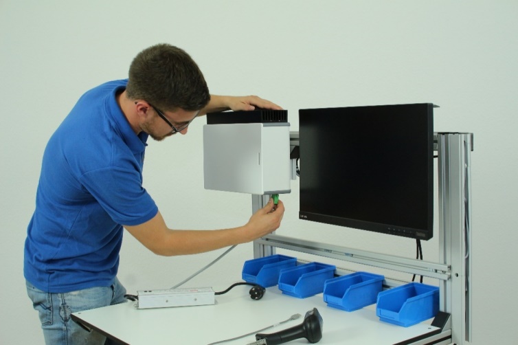
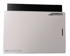
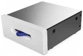
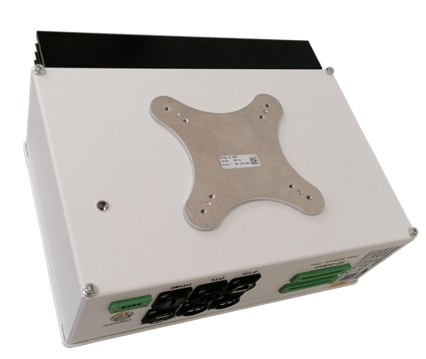
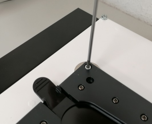
The SWA is delivered with an adapter plate on the back of the device. The adapter plate allows you to attach a VESA-compliant mount (75/100, M4 thread) to integrate the SWA into your workstation.
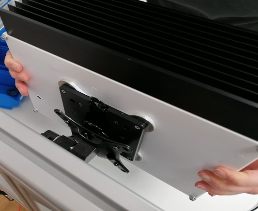
If you have chosen our quick-change device (STAMA No.: 3180), please follow the instructions on the next page.

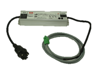
Connector pin assignment:
The image shows the polarity of the connector.
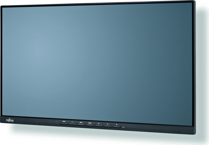
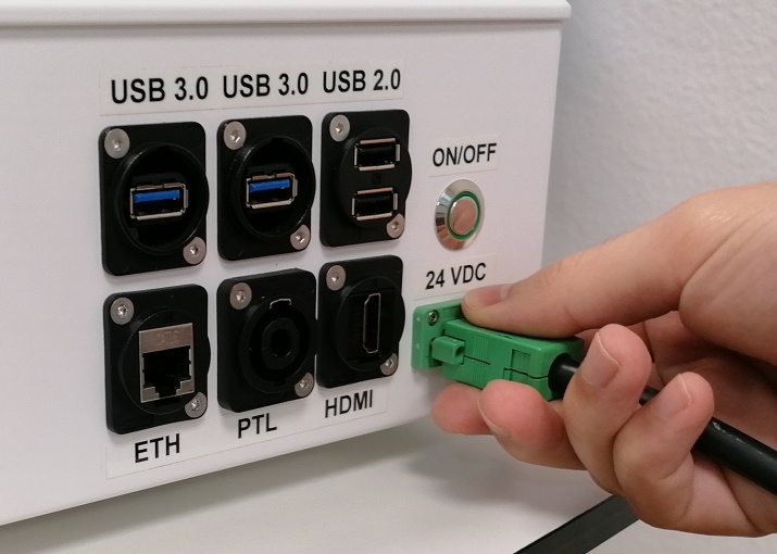
Setting up touch function: Connect the USB cable to the monitor and the USB 3.0 port of the SWA; additionally insert the USB-B connector into the monitor port.
Scanner: Connect to one of the USB 2.0 ports of the SWA. More information in QS: 0.6-QS_Scanner
Network: Connect the SWA to the network via the Ethernet socket.
Monitor: Connect the monitor to the SWA via HDMI cable.
Additional devices can be connected to the SWA using a USB hub (STAMA No. 3576).
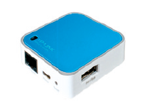
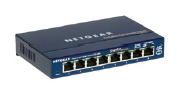
Optionally, you can purchase a network switch (STAMA No. 3635) for connecting multiple network devices, or a WiFi access point (STAMA No. 3578) to connect a wireless device to the SWA.
Connect the pick-to-light connector to the PTL port. More information in QS: 2.1-QS_PTL
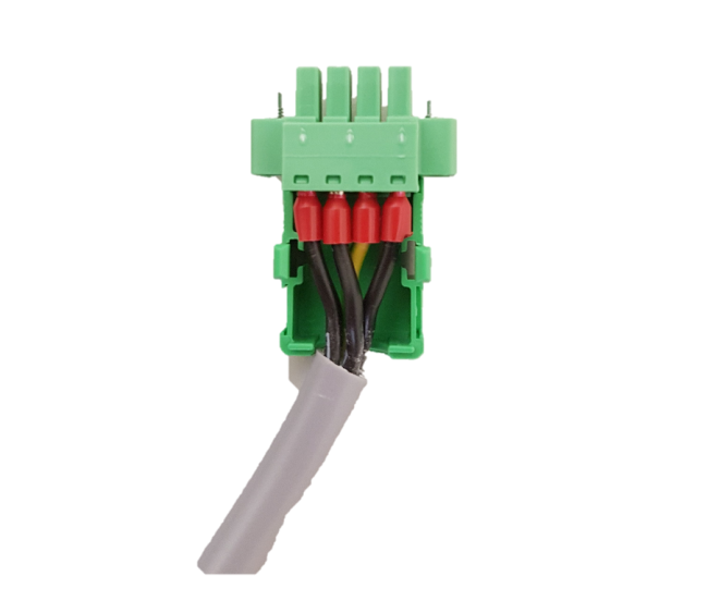
Connect the digital inputs and outputs to the SWA using the supplied connectors.
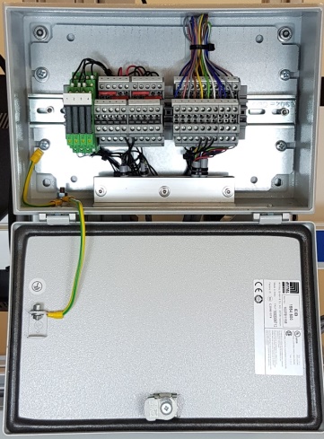
Optional terminal box (STAMA No.: 3574 / 3575): For wiring your inputs and outputs.
Place the wires onto the corresponding terminals of the connector, then insert the connector into the input socket.
To connect an input, connect the SWA to ground and wire the desired input according to the diagram shown.
Warning: Observe the maximum voltage of 24 VDC. Exceeding the voltage or reverse polarity will destroy the device. Liability is excluded for improper connections.
Place the wire onto the corresponding terminals of the connector, then insert the connector into the output socket.
To switch an output, supply the output terminal with 24 V and ground. Connect your load according to the diagram shown.
Warning: Observe the maximum current of 500 mA. Exceeding this will destroy the device. Liability for the device is excluded in case of improper overloading.
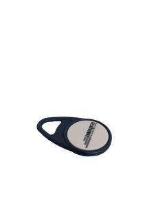
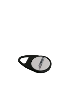
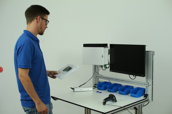
Every SWA server and SWA client is equipped with an internal key reader. Three keys are included, which can be programmed with different user data. More information: QuickStep 0.2-QS_Assistant
External Key Reader: The functionality and setup are identical to the internal key reader. It connects via a USB port of the SWA.
Once everything is connected, start the SWA by pressing the on/off switch once. If power is supplied, the LED ring should light up green. Otherwise, please check the power supply.
| Abbreviation | Description |
|---|---|
| ELAM | Electronic Line Integration of Assembly Systems |
| ETH | Ethernet |
| I/O | Input / Output |
| Key | RFID chip for employee identification |
| PTL | Pick to Light |
| QS | QuickStep, quick guide for the ELAM system |
| STAMA No. | Internal article number at Armbruster Engineering |
| SWA | Smart Work Assistant |


